NZX 2500
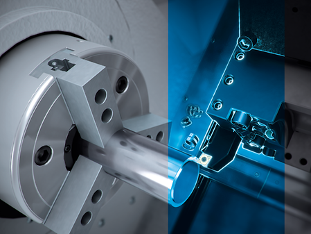
Overwhelming Manufacturing Capability Standing Out in Shaft & Flange Machining
Highlights
Milling (option)
- Turret equipped with BMT (Built-in Motor Turret)
- High-speed rotary tool spindle: 10,000 min-1
- Maximum rotary tool spindle torque:40 N•m (29.5 ft・lbf) <3 min.> [Option]
High rigidity
- Slideways are used for all axes
- High tailstock rigidity
- Lightweight yet robust body achieved through FEM analysis
High precision
- High-resolution direct scale feedback (option)
- Improved machining accuracy thanks to the thermally stable structure

Reliability
- Sophisticated spindle labyrinth structure
- Outstanding chip disposal
Application Examples
Control & Software
Experience the speed of digital transformation (DX)
Revolutionize your operations, unlock new opportunities, increase efficiency and promote sustainability by reducing power consumption – while gaining a strong competitive advantage.

- DMG MORI specific user interface optimized for vertical screen orientation
- Fully customizable flexible display with up to 10 windows and arrangement in window sets
- 3D collision control and machining simulation
- Comprehensive machining cycles
- Tool Management System
- Standardized app-based user interface independent of the CNC control system
- Possibility of connecting the machine to the company organization
- Application for simple operation, extended spindle hours and increased energy efficiency
- Future-proof thanks to online update options
- Prepared for CELOS Xchange cloud connection
- NETserivce: Remote diagnostics and remote maintenance
- MDC: Standardized machine data output in OPC UA, MT connect and MQ TT formats
- Service Agent: Integrated maintenance manual
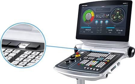
- 24” multitouch screen with space saving vertical screen orientation
- Full size tactile keyboard
- Two potentiometers for feed and rapid traverse
- Hybrid bar with display buttons for individual button functions
- SMARTkey in credit card format
- Ergonomic angle adjustment

- DMG MORI specific user interface
- Extensive machining cycles
- Flexible display through 6-window display and arrangement in window sets
- 3D collision control and machining simulation
- Extensive machining cycles
- Tool Management System
- Possibility of connecting the machine to the company organization
- NETserivce: Remote Diagnostics and Remote Maintenance
- IoTconnector: Standardized machine data output in the formats OPC UA, MT connect and MQ TT
- Service Agent: Integrated Maintenance Guide
- 21,5” multitouch screen
- Lower touch screen with individual and adaptive functions
- SMARTkey with integrated USB drive
- Ergonomic angle adjustment

- DMG MORI specific user interface
- Extensive machining cycles
- Flexible display through 6-window display and arrangement in window sets
- 3D collision control and machining simulation
- Extensive machining cycles
- Tool Management System
- Possibility of connecting the machine to the company organization
- NETserivce: Remote Diagnostics and Remote Maintenance
- IoTconnector: Standardized machine data output in the formats OPC UA, MT connect and MQ TT
- Service Agent: Integrated Maintenance Guide
- 21,5” multitouch screen
- Lower touch screen with individual and adaptive functions
- SMARTkey with integrated USB drive
- Ergonomic angle adjustment

- Machining also on machines without Y-axis
- Highly productive without milling the individual surfaces
- Dialog-guided programming thanks to the technology cycle

- Oscillating movement of the feed axis results in air cutting, which leads to effective chip size reduction
- For external longitudinal turning of internal and external diameters, facing, drilling and grooving*
- Integrated safety function checks plausibility of parameter entries
* For inclined surfaces, a step pattern results because the feed can only be oscillated in one axis at a time.

- The chip length can be practically determined by the cycle and is independent of the material
- No more process interruptions, as chip balls are avoided
- Easy setting on the HMI with high operating safety


- Perfect combination of 6-sided complete machining and tailstock function
- Automatically load and unload a tailstock centre into the chuck of the main spindle or counter spindle via the milling spindle and into the mgazine
- Support of long and slender workpieces on the main spindle thanks to the synchronous counter spindle tip
- Higher component accuracy due to automatic change without opening the door (heat flow constant)
- Position-locking the spindle with the tip leads to increased process safety


- NEW: On-Point Threading - Position oriented thread production
- Free definition of contours, pitches and gears possible
- Creation of large transmission threads, which can not be manufactured by simple thread chasing
- Trapezoidal, buttress and knuckle thread easily programmable at the machine
- Screw conveyor with any profile geometry
- Ball screw nut with cross holes simple to realize


Highlights
- Producing profiles with undercut due to the profile splitting option.
- Applying standard tools and tool holder for left and right sided machining of the flanks
- Surface quality of Ra 0,3 an CrNi-Alloys possible

- Prevention of damage due to tool breakage or tool overload
- Sensorless with automated learning of load limits
- For turning, milling and drilling (up to 3 mm diameter)
- NEW: User interface on CELOS SideScreen
- NEW: Powerful algorithm for efficient monitoring after the first workpiece
- Protection Package: Perfect supplement to MPC Lathes. Price advantage (approx. 40%)
- Save the monitoring limits for each tool and every cutting edge in the program


- Superposition of the turning movement by additional X- and Y-traverses
- Applicable for turning and milling
- Eccentric geometries easy to manufacture
- Exact axis coupling and synchronization in the background


- By pushing the associated key the X- axis and the Y-axis travel to the positive end-positions for external machining
- Ideally suited to prepare the work space for set-up and alternatively also as an emergency rescue function.

- Easy operation when setting up multi - channel machinery
- Possibilty of a fast response during external machining as a rescue function

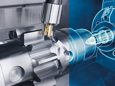
- Programming of the gearing parameters via dialog input
- For spur gear, helical gear and worm gear
- Gear cutters and disk cutters can be used
- Maximized tool life by shifting of the cutter
- Achievable quality ≤ DIN 7
- Gear profile modifications easy to handle
- Use of regrinded tools
- Error prevention by monitoring (e. g. wrong axis cross angle, or wrong turning speed, or turning direction)

- Efficient use of multi-tip turning tools with more than one cutting edge on turn & mill
- Several "sister tools" on one main tool holder
- Reduction of tool change times
- Saves tool magazine space


- Easy to operate through three parameters and without additional sensors
- Avoiding vibrations by means adaptation of the speed
- Application for the main spindle and counter spindle, or for milling machines with FD tables with Direct Drive

- No manual intervention by the operator
- Identical repeatability for all components
- Increased process safety for special applications by avoiding vibrations. example, When using long thin drills or for milling parts with critical clamping

- Straight and helical external or internal spur gears and splines
- Arrow teeth with tooth offset Turn-mill machines
- Ball-shaped toothing by mathematical transformation of the 6th virtual axis

- Productive complete processing
- Cost-effective gear cutting on standard machine with standard tools
- Flexible for different gear geometries
- Quality inspection in the process
- Program creation based on blank drawings and gear data
- Optimization of workpiece orientation e.g. after heat treatment
- Interface for coordinate measuring device (Klingenberg, Leitz, Zeiss)

Service & Training
Comprehensive carefree service and training for your production
Take advantage of our full-service offering and hands-on training to maximize machine performance and minimize downtime. With comprehensive maintenance packages, original spare parts and tailored training programs, we can take your production and your team to the next level.
Downloads & Technical Data
Special technical articles, analyses and background information on topics that move our industry.
- Unlimited product experience – unlock all technical machine data and product brochures.
- Exclusive videos, technical articles, whitepapers and blog articles with deep insights into the DMG MORI product world.
- Personalised access to other DMG MORI Platforms, including Event Platform, Media Library and much more.
Discover exclusive content with your DMG MORI Account.
- Unlimited product experience – unlock all technical machine data and product brochures.
- Exclusive videos, technical articles, whitepapers and blog articles with deep insights into the DMG MORI product world.
- Personalised access to other DMG MORI Platforms, including Event Platform, Media Library and much more.
Learn more about the DMG MORI Account.
Get access to many useful digital functions and services and have all important data at a glance. With a central DMG MORI Account, you can use all services around the clock from anywhere and with any device.
- Unlimited product experience – unlock all technical machine data and product brochures.
- Exclusive videos, technical articles, whitepapers and blog articles with deep insights into the DMG MORI product world.
- Personalised access to other DMG MORI Platforms, including Event Platform, Media Library and much more.
Learn more about the DMG MORI Account.
Unlock access to your Share Hub and many other functions and services. With a central DMG MORI Account, you can use all services around the clock from anywhere and with any device.
- Unlimited product experience – unlock all technical machine data and product brochures.
- Exclusive videos, technical articles, whitepapers and blog articles with deep insights into the DMG MORI product world.
- Personalised access to other DMG MORI Platforms, including Event Platform, Media Library and much more.
Learn more about the DMG MORI Account.
For general enquiries, please use our contact form.
For service and spare parts enquiries please use the my DMG MORI portal: https://mydmgmori.com/
Thank you very much for your interest.
Please fill out the form below to download the requested document.
If you accept the storage of cookies, this form appears only once during your visit.


